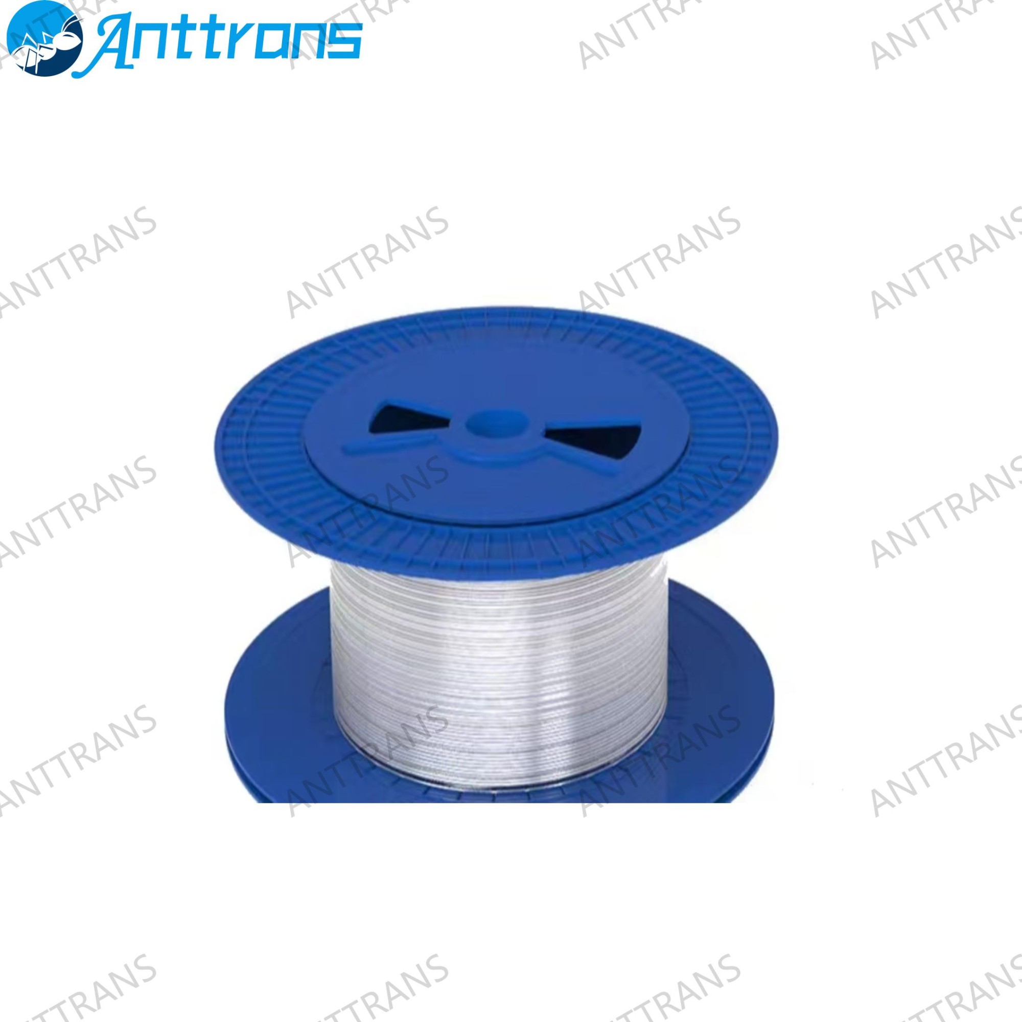
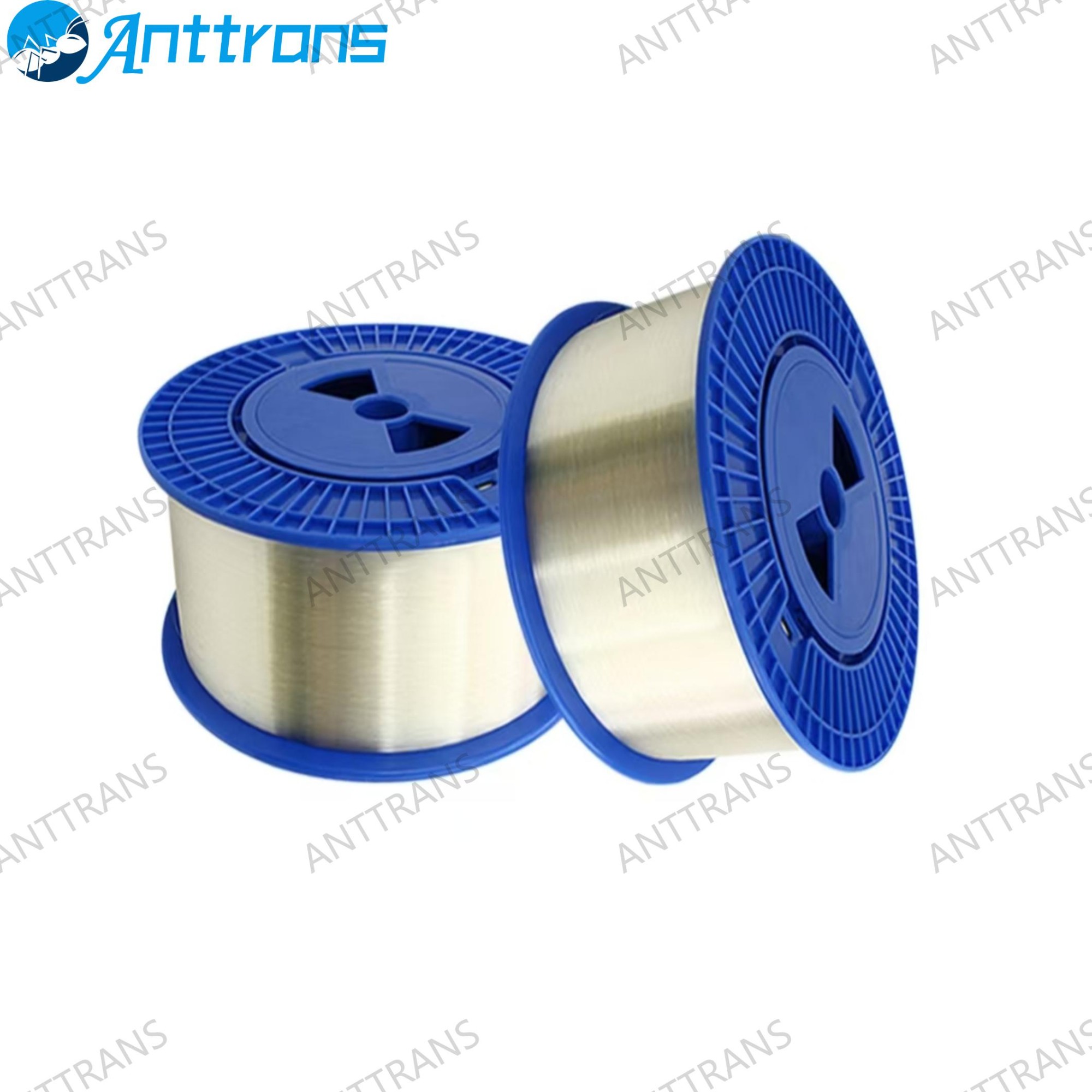
Single Cladding Silica Optical Fiber
- Product Item : AT-61053
- Category: Optical Fiber, Quartz & Semiconductor Consumables
- Product description:
Product Introduction
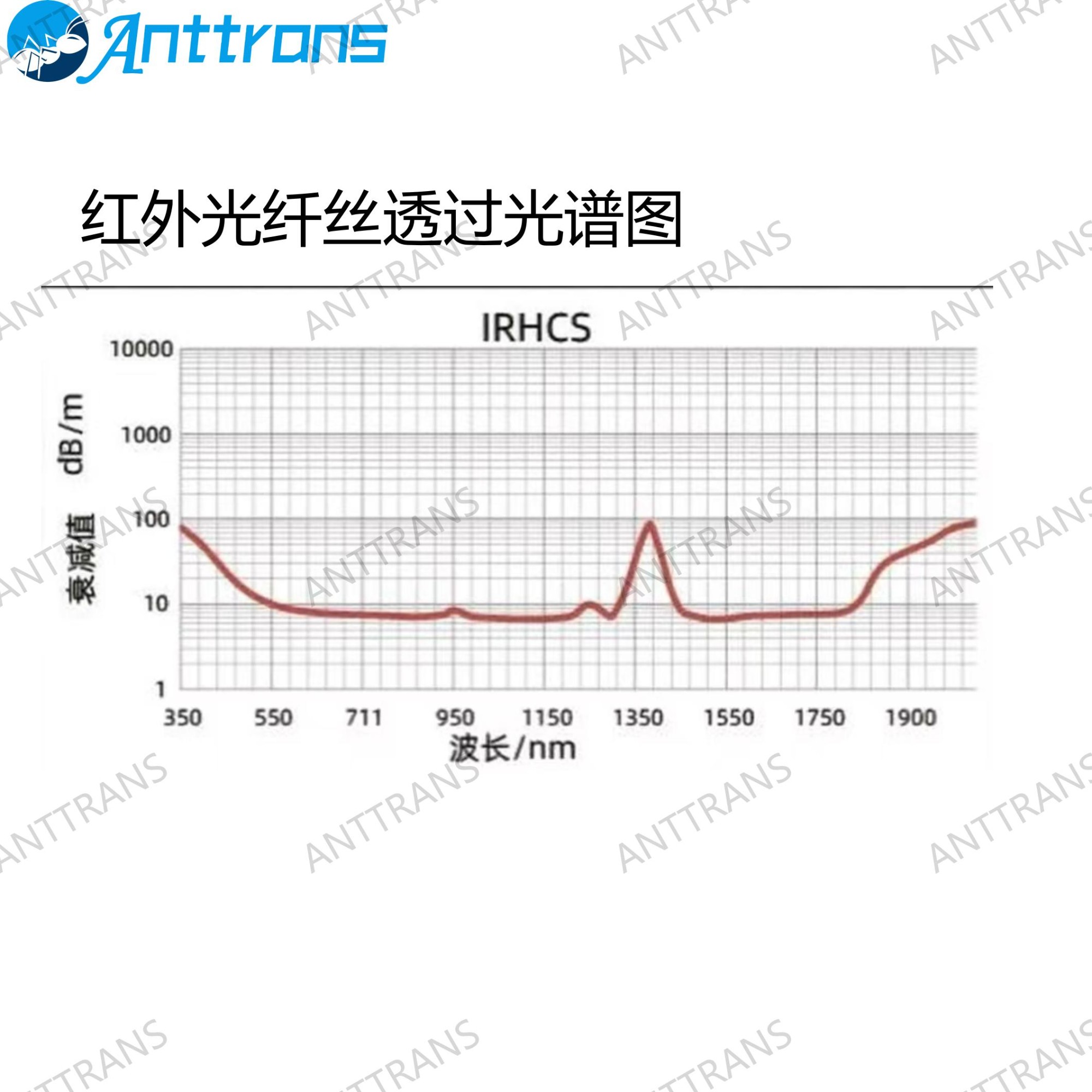
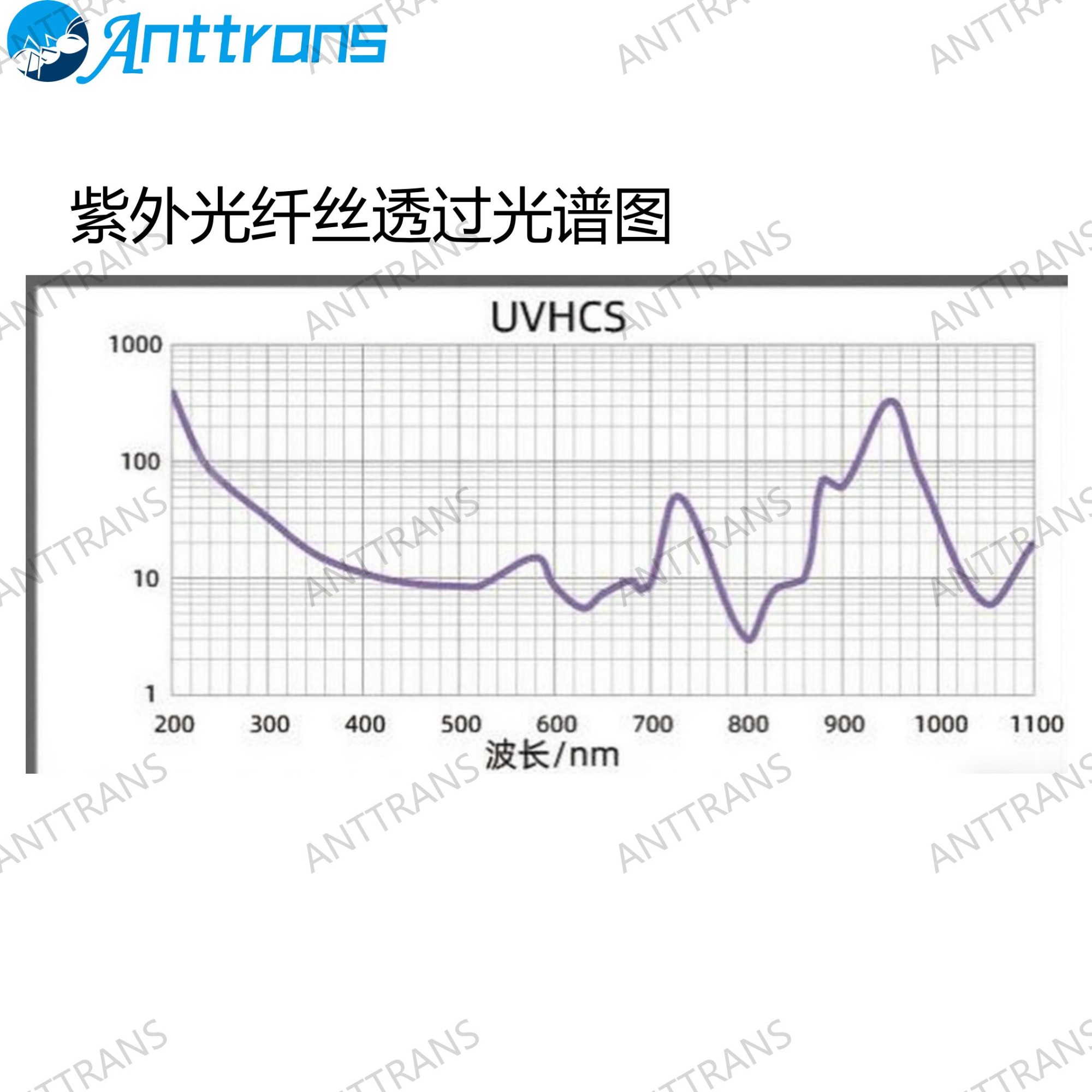
Single Cladding Silica Optical Fiber (PCS) employs high-refractive-index pure silica glass as the core material and low-refractive-index polymer as the optical cladding. Its spectral transmission range spans from UV: 200~1100 nm to IR: 350~2100 nm, offering superior light transmission efficiency in both ultraviolet and infrared wavelength bands.
Applications
It is utilized in the fabrication of light-transmitting bundles and cables for the transmission of energy and signals.
Product Parameters
Performance Indicators:
|
Optical Performance Classification |
Transmittance (%/m)* |
Numerical Aperture |
Coating Material |
Long-Term Temperature Resistance (℃) |
Mechanical Characteristic Screening Strength (Kpsi) |
Long-Term Bending Radius |
Short -Term Bending Radius |
|
ATUV |
≥99.6 |
0.37±0.02 |
Silicone Rubber |
-50~250 |
≥100 |
300 D* |
100 D* |
|
ATIR |
≥99.6 |
0.37±0.02 |
Fluoropolymer |
-180~250 |
≥100 |
300 D* |
100 D* |
Note: Transmittance measured at 632.8 nm; D represents the outermost diameter of the fiber grating.
Specifications:
Silicone Rubber Coated Silica Optical Fibers:
|
Specification Model |
Core Diameter/μm (Pure Silica)* |
Optical Cladding/μm (Silicone Rubber) |
Minimum Bending Radius/mm |
|
AT 100/220 P-US |
100 |
220 |
10 |
|
AT 150/250 P-US |
150 |
250 |
15 |
|
AT 200/350 P-US |
200 |
350 |
20 |
|
AT 300/500 P-US |
300 |
50 0 |
30 |
|
AT 400/550 P-US |
400 |
550 |
40 |
|
AT 500/700 P-US |
500 |
70 0 |
50 |
|
AT 600/900 P-US |
600 |
900 |
60 |
|
AT 700/1000 P-US |
700 |
1000 |
70 |
|
AT 800/1200 P-US |
800 |
1200 |
80 |
|
AT 900/1300 P-US |
900 |
1300 |
90 |
|
AT1000/1400 P-US |
1000 |
1400 |
100 |
Note: 62% core diameter refers to the proportion of the core within the overall fiber structure.
Thin Coated/Thin Sheathed Silica Optical Fibers (Fluoropolymer Coated):
|
Specification Model |
Core Diameter/μm (Pure Silica)* |
Optical Cladding/μm (Hard Resin) |
Protective Layer/μm (Teflon) |
Minimum Bending Radius/mm |
|
AT200/230/500 H-UA |
200 |
230 |
500 |
20 |
|
AT300/330/650 H-UA |
300 |
330 |
650 |
30 |
|
AT400/430/730 H-UA |
400 |
430 |
730 |
40 |
|
AT600/630/750(1040) H-UA |
600 |
630 |
750/1040 |
60 |
|
AT8 00/830/1040 H-UA |
800 |
830 |
1040 |
80 |
|
AT1000/1035/1500 H-UA |
1000 |
1035 |
1500 |
100 |
|
AT1500/1550/2000 H-UA |
1500 |
1550 |
2000 |
150 |
Note: Deviation ±2%.
Fluoropolymer Coated Silica Optical Fibers:
|
Specification Model |
Core Diameter/μm* |
Coating Layer/μm |
Minimum Bending Radius/mm |
|
AT 100/130 P-US |
100 |
130 |
10 |
|
AT150/180 P-US |
150 |
180 |
15 |
|
AT200/230 P-US |
200 |
230 |
20 |
Note: Deviation ±2%.
Fluorinated Coating Dispersed Silica Optical Fibers:
|
Specification Model |
Core Diameter/μm* |
Coating Layer/μm |
Minimum Bending Radius/mm |
|
AT200/290 P-US |
200 |
290 |
20 |
Note: Deviation ±2%.