
Industry-news
light diffraction
Diffraction of Light
01 Huygens-Fresnel Principle
The secondary wavelets emitted from each point on the wavefront superpose in space, and the intensity of the wave at each point in the superposition region is determined by the coherent superposition of these wavelets.
02 Types of Diffraction
According to the relative positions of the light source, obstacle, and receiving screen, diffraction can be classified into two types: Fresnel diffraction (near-field diffraction) and Fraunhofer diffraction (far-field diffraction). In Fraunhofer diffraction, the distances from the light source and the receiving screen to the obstacle are infinitely far, so the light is parallel to the obstacle, making this type of diffraction relatively simple.
03 Single-Slit Fraunhofer Diffraction
Fresnel Half-Wave Zone Method: The distribution pattern of bright and dark fringes in single-slit diffraction is obtained using the Fresnel half-wave zone method, as briefly explained below:
|
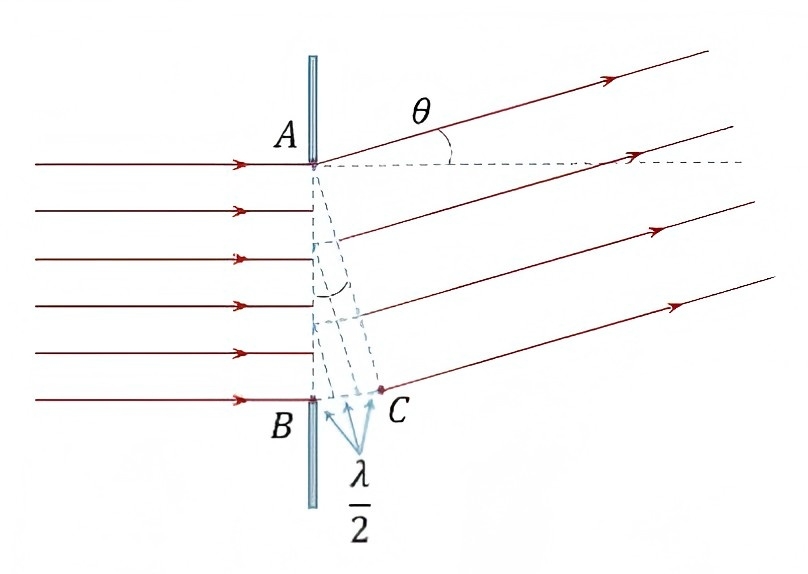
The coordinates on the screen correspond one-to-one with the diffraction angles through the single slit, allowing us to analyze the coherence situation at specific diffraction angles to determine the corresponding coordinates.
Divide the maximum optical path difference BC by λ/2 and draw perpendiculars from the division points to BC, dividing the slit width into corresponding numbers of zones called half-wave zones. The light rays in adjacent half-wave zones correspond one-to-one from top to bottom, with an optical path difference of λ/2, resulting in destructive interference. Therefore, if the number of half-wave zones is even, the convergence point P is a dark fringe; if odd, P is a bright fringe. If it's a non-integer, it lies in the transition region between bright and dark.
Maximum Optical Path Difference: For light at a specific diffraction angle, there exists a maximum optical path difference when passing through the single slit. The screen coordinates correspond one-to-one with the diffraction angle θ of the single slit. The maximum optical path difference is given by BC = a sinθ, where a is the slit width and θ is the diffraction angle.
Half-Wave Zone Division and Fringe Pattern: Divide the maximum optical path difference by λ/2 to divide into half-wave zones. If the number of half-wave zones is even, P is a dark fringe; if odd, P is a bright fringe.
Fringe Conditions:
Bright fringes: a sinθ = ±(2k+1)λ/2 (k=1,2,…)
Dark fringes: a sinθ = ±kλ (k=1,2,…)
Central Bright Fringe Characteristics:
Half-angle width (approximate): θ1 = λ/a
Line width: Δx0 = 2fλ/a, where f is the lens focal length.
Other Order Fringe Characteristics:
Angular width (approximate): Δθ ≈ λ/a
Line width (approximate): Δx ≈ fλ/a
04 Circular Aperture Fraunhofer Diffraction
Airy Disk: The central bright spot in circular aperture diffraction, its half-angle width, which is the diffraction angle of the first dark fringe, is given by sinθ1 = 1.22λ/D, with an approximate half-angle width of θ1 ≈ 1.22λ/D.
Rayleigh Criterion: When the center of the Airy disk of one object point just coincides with the edge (first minimum) of the Airy disk of another object point, these two object points can just be resolved by the optical instrument.
Minimum Resolvable Angle: When two object points can just be resolved by the optical instrument, the angle subtended by their connecting line at the center of the instrument is called the minimum resolvable angle, δθ = 1.22λ/D.
Resolving Power: The reciprocal of this angle is defined as the resolving power of the instrument, R = D/(1.22λ).
05 Grating Diffraction
Grating Concept: A structure with periodic intervals of transparent and opaque parts that can equally divide the wavefront, called a grating. The width of the transparent part is a, and the width of the opaque part is b, with their sum d = a + b called the grating constant.
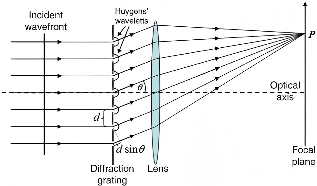
Grating Equation: The result of the combined effect of single-slit diffraction and multi-slit interference, i.e., multi-beam interference under the background of single-slit diffraction. The position of the principal maximum fringes is determined by the grating equation d sin θ = ±kλ (k=0,1,2,…), but is also modulated by the single-slit diffraction fringes. As shown in the figure, purple represents the light intensity distribution of pure multi-slit interference, blue represents that of single-slit diffraction, and red represents grating diffraction with both effects present. The brightness of the principal maximum fringes is no longer uniform and may exhibit missing orders.
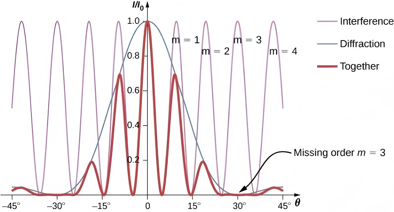
Missing Order Phenomenon: When the diffraction angle of a principal maximum coincides with that of a dark fringe in single-slit diffraction, that principal maximum fringe will not appear, known as the missing order phenomenon. The condition for missing orders is when an angle θ simultaneously satisfies the dark fringe formula of single-slit diffraction d sinθ = kλ and the grating equation d sinθ = k'λ, hence k' = (d/a)k (k=1,2,3,…).
Grating Diffraction Pattern Characteristics:
Bright, thin, and sparsely distributed fringes, with equal spacing at small angles.
N-1 dark fringes and N-2 secondary bright fringes between adjacent principal maxima (N is the number of grating slits).
06 X-Ray Diffraction
X-Rays: A type of electromagnetic wave with a very short wavelength, discovered by Röntgen.
Bragg's Law: Provides the law governing the diffraction bright fringes of X-rays, where the diffraction angles satisfy 2d sinθ = kλ (k=1,2,3,…), with d being the lattice constant and θ the diffraction angle.
