Industry-news
Research on the Influence of Coil Size and Layout on the Temperature Field of a 12-Inch Silicon Carbide Single Crystal Growth Induction Furnace
Silicon carbide (SiC) possesses properties such as a wide bandgap, high thermal conductivity, high electron saturation migration rate, and high breakdown electric field, making it an ideal semiconductor material for manufacturing optoelectronic devices, high-voltage and high-power devices, and high-temperature electronic devices. Currently, the industrial growth of SiC single crystals primarily relies on the physical vapor transport (PVT) technique. The quality and growth rate of single crystals largely depend on the temperature field distribution within the furnace . A lower radial temperature gradient at the seed crystal can effectively improve the crystal growth shape, reduce thermal stress within the crystal, and thus enhance the crystal growth quality. Conversely, a higher longitudinal temperature gradient in the growth chamber is beneficial for increasing the crystal growth rate. Common heating methods for PVT SiC single crystal furnaces include induction and resistance heating, with induction furnaces being widely adopted due to their simple structure. The temperature field within the furnace is mainly influenced by the induction coil and the parameters of the crucible insulation layer.
Several studies have reported on the influence of induction coil size and layout parameters on the temperature field of SiC single crystal growth furnaces. For instance, Wang Yingmin et al. simulated the effect of the relative position of the coil to the crucible on the temperature field within a 3-inch SiC crystal growth furnace, observing that as the crucible position rose, the radial temperature difference at the crystal growth surface decreased, while the axial temperature difference between the powder and the growth chamber increased, and the furnace heating efficiency decreased. Zhang Zuishe et al. employed the finite element method to study the impact of coil position and turn spacing on the temperature field of a 2-inch SiC crystal growth furnace, finding that raising the coil or increasing the turn spacing reduced the axial temperature gradient within the growth chamber, shifted the high -temperature heating region upwards, and decreased the system heating efficiency. Their research also investigated the influence of the gap between the induction coil and the insulation layer on the heating efficiency of the SiC single crystal growth furnace, discovering that reducing the gap could enhance the system heating efficiency and shorten the time required to reach thermal equilibrium. Zhang et al. studied the effects of the excitation direction and excitation frequency of the induction coil on single crystal growth in a 6-inch SiC growth furnace, noting that downward displacement of the coil could alleviate the issue of decreasing axial temperature gradient in the growth chamber. Yang et al. simulated the influence of dual induction coil spacing control on the temperature field of an 8-inch SiC crystal growth furnace, finding that dual induction coils could flatten the isothermal shape, thereby reducing thermal stress within the single crystal.
Most of the aforementioned literature focuses on SiC single crystal growth processes for sizes of 8 inches and below. However, larger crystal sizes are advantageous for device integration and cost reduction. Nevertheless, as the crystal size increases from the outside to the inside, thermal resistance also increases, making temperature control at the crystal growth interface more complex. Therefore, it is necessary to study the temperature field for larger crystal sizes. This paper utilizes ANSYS software to conduct a steady-state simulation of the temperature field within a 12-inch Si C single crystal growth furnace, investigating the influence of coil size and layout parameters such as the relative position of the induction coil to the crucible, the height ratio between the coil and the crucible, the turn height ratio, the coil inner diameter, and the turn width on the temperature field. The results hold significant reference value for guiding the design and optimization of 12-inch SiC single crystal growth induction furnaces.
Numerical Model
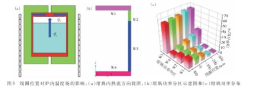
ANSYS Fluent was employed to numerically simulate the temperature field within the SiC single crystal growth induction furnace, with its structure depicted in Figure 1(a). SiC powder is located at the bottom of the crucible, and the seed crystal is positioned at the top. Graphite felt wraps the crucible for insulation, with upper and lower measurement ports. The induction coil is situated outside the graphite felt, with a double-layer water-cooled quartz tube between the coil and the graphite felt. The furnace's initial dimensions are provided in Table 1, and the coil position Δ represents the axial distance between the center of the induction coil and the center of the crucible, with a negative sign indicating that the coil center is lower than the crucible center. The coil consists of 12 turns with a hollow water-cooled structure, as illustrated in Figure 1(b). A 2D axisymmetric model was used for mesh generation, with quadrilateral elements chosen. The global mesh edge length was set to 5 mm, while the edge lengths for the inner and rotational axis were set to 1 mm.
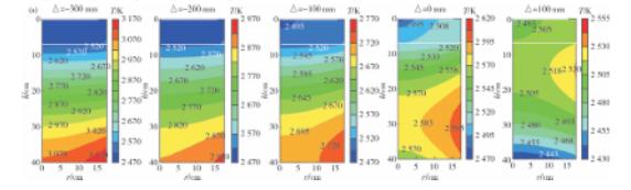
Table 1: Initial Dimensions of the Induction Furnace for SiC Single Crystal Growth
|
Parameter |
Dimension (mm) |
|
Crucible Inner Diameter (ID) |
70 |
|
Crucible Height (L) |
[ Value not provided in original text] |
|
Coil Inner Diameter (n) |
[Value not provided in original text, but mentioned in text as a parameter] |
|
Coil Height (II) |
20 |
|
Coil Position (Δ) |
-11 |
|
Furnace Length |
[Value not provided in original text] |
|
Furnace Thickness |
1 |
|
Upper Measurement Port Diameter |
[Value not provided in original text] |
|
Lower Measurement Port Diameter |
[Value not provided in original text] |
|
Graphite Felt Thickness |
15 |
|
Insulation Layer Side Thickness |
[Value not provided in original text, but mentioned in text as a parameter] |
|
Insulation Layer Bottom Thickness |
6 |
During the Fluent thermal field simulation, a 2D axisymmetric model was used. Natural convection was modeled using the k-ε model, and radiation was simulated using the discrete ordinates (DO) radiation model, assuming all participating radiation surfaces were diffuse gray surfaces and neglecting gas absorption and scattering effects. The material physical property parameters of the single crystal growth furnace are listed in Table 2, including density, specific heat capacity, and thermal conductivity. Some parameters exhibit temperature dependence and were set using formulas. The boundary conditions are as follows: 1) The furnace interior gas is assumed to be incompressible and ideal, with a working pressure of 1 kPa; 2) No-slip boundary conditions are applied at the solid-gas interfaces; 3) The radiation coefficient of the graphite felt outer wall to the environment is 0.8, and the convection heat transfer coefficients for the top, side, and bottom of the insulation layer are 0.5, 2, and 0.4 W/(m·K), respectively; 4) The ambient temperature is set to 45°C.
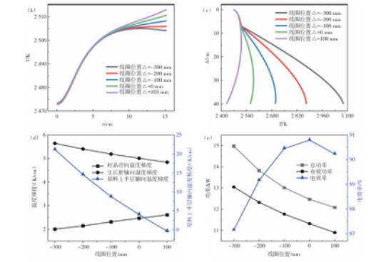
Table 2: Physical Properties of Materials for the SiC Single Crystal Growth Induction Furnace
|
Material |
Density (kg/m³) |
Specific Heat Capacity (J/(kg·K)) |
Thermal Conductivity (W/(m·K)) |
Emissivity |
|
Graphite |
1600 |
710 |
120-160 (temperature-dependent) |
0.8 |
|
SiC Single Crystal |
3210 |
670 |
450 (constant) |
0.5 |
|
SiC Powder |
1600 |
[Value not provided, but similar to single crystal] |
[Value not provided, but likely similar] |
0.6 |
|
Graphite Felt |
160 |
[Value not provided, but likely similar to graphite] |
[Value not provided, but likely low] |
[Not applicable, as it's an insulation material] |
The heat source within the furnace originates from the induction heating of the crucible and graphite felt, neglecting the induction heating of the powder, seed crystal, and protective shell. Maxwell's equations were used for electromagnetic simulation, transferring the Joule losses obtained from electromagnetic simulation to Fluent as heat sources for thermal field calculations. In the electromagnetic simulation, a 2D axisymmetric steady-state eddy current model was employed. The coil material is copper, with a relative electrical conductivity of 1, an electrical conductivity of 5.5×10^7 S/m, and a density of 8911 kg/m³. The crucible material is graphite, with a relative electrical conductivity of 1, an electrical conductivity of 10^5 S/m, and a density of 1820 kg/m³. The graphite felt has a relative electrical conductivity of 1, an electrical conductivity of 153.56 S/m, and a density of 160 kg/m³. The boundary conditions include: 1) A balloon boundary for the computational domain; 2) Series connection between each turn of the coil, with the same current applied to each turn; 3) An induction coil frequency of 10 kHz.
Both the thermal and magnetic fields were simulated in steady-state mode. The center of the lower surface of the seed crystal was selected as the control point, and the current in the coil was adjusted to maintain the control point temperature at 2200°C±2°C. For convenience in research, the electrical efficiency was defined as the ratio of the Joule heat in the crucible and insulation layer to the sum of the Joule heat in the crucible, insulation layer, and coil. When the coil center is lower than the crucible center, the position Δ is taken as negative, and h represents the distance from the top of the seed crystal, while r represents the radius from the centerline of the seed crystal. The definitions of the radial temperature gradient at the seed crystal surface (G_r,s), the axial temperature gradient in the growth chamber (G_a,c), the radial temperature gradient at the powder surface (G_r,p), and the axial temperature gradient within the powder (G_a,p) are as follows:
G_r,s = (T_s,e - T_s,c) / R_s
G_a,c = (T_c,t - T_c,b) / H_c
G_r,p = (T_p,e - T_p,c) / R_p
G_a,p = 2 × (T_p,t - T_p,b) / H_p
Where: T_s,e is the edge temperature of the lower surface of the seed crystal, T_s,c is the center temperature of the lower surface of the seed crystal, T_p,e is the center temperature of the upper surface of the powder, T_p,c is the edge temperature of the upper surface of the powder, T_p,t is the temperature at the center height of the powder, T_p,b is the temperature at the bottom of the powder, R_s is the radius of the seed crystal, R_p is the radius of the powder, H_c is the height of the growth chamber, and H_p is the height of the powder. The subscripts S, C, and P represent the seed crystal, growth chamber, and powder, respectively, while the subscripts r, a, s, i, c, and e represent radial, axial, surface, internal, center, and edge, respectively.
Simulation Results and Analysis
2.1 Influence of Coil Relative Position on the Temperature Field
Assuming the center temperature of the seed crystal growth surface is 2200°C and the coil frequency is 10 kHz, the influence of the relative position of the coil to the crucible on the temperature field within the induction furnace is depicted in Figure 2. Analyzing the temperature distribution cloud map within the furnace, it is observed that as the coil position decreases, the overall temperature field within the furnace shifts downward, and the maximum temperature within the powder increases. When the coil position is below -200 mm, the maximum temperature within the powder exceeds 3000 K. As shown in Figures 2(b) and 2(c), when the coil position varies between 100 mm and -400 mm, its influence on the radial temperature distribution of the seed crystal is mainly concentrated at the outer edge of the seed crystal, while its impact on the central axis temperature is reflected in the powder, with a relatively small effect on the growth chamber and the axial temperature of the seed crystal. Analysis in Figure 2(d) indicates that as the coil position decreases, the radial temperature gradient of the seed crystal decreases, while the axial temperature gradient of the growth chamber increases. A smaller radial temperature gradient (G_r,s) at the seed crystal surface can reduce stress and dislocation distribution within the crystal, while a larger axial temperature gradient (G_a,c) in the growth chamber can accelerate the crystal growth rate. Therefore, under the condition that the powder does not exceed the temperature limit, the optimal coil position is -200 mm. Compared to a coil position of 0 mm, the radial temperature gradient of the seed crystal decreases by approximately 13%, and the axial temperature gradient of the growth chamber increases by 8%. Figure 2(e) shows that the electrical efficiency is highest when the coil relative position is 0 mm. As the coil moves away from the 0 mm position, the electrical efficiency decreases. When the coil position is -200 mm, the electrical efficiency decreases by 1.6%. It is evident that optimizing the furnace temperature field through coil position adjustment only slightly reduces the electrical efficiency.