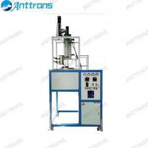
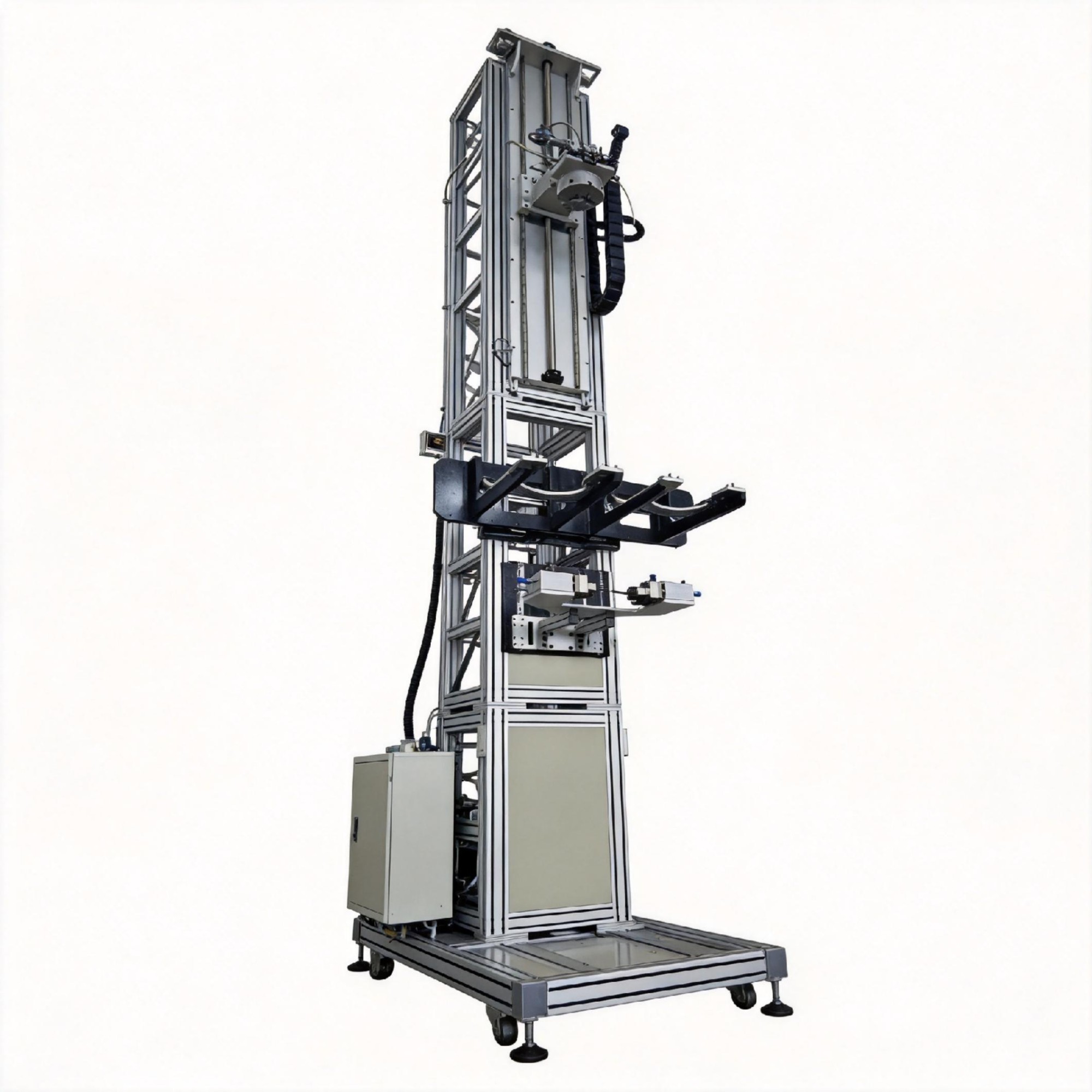
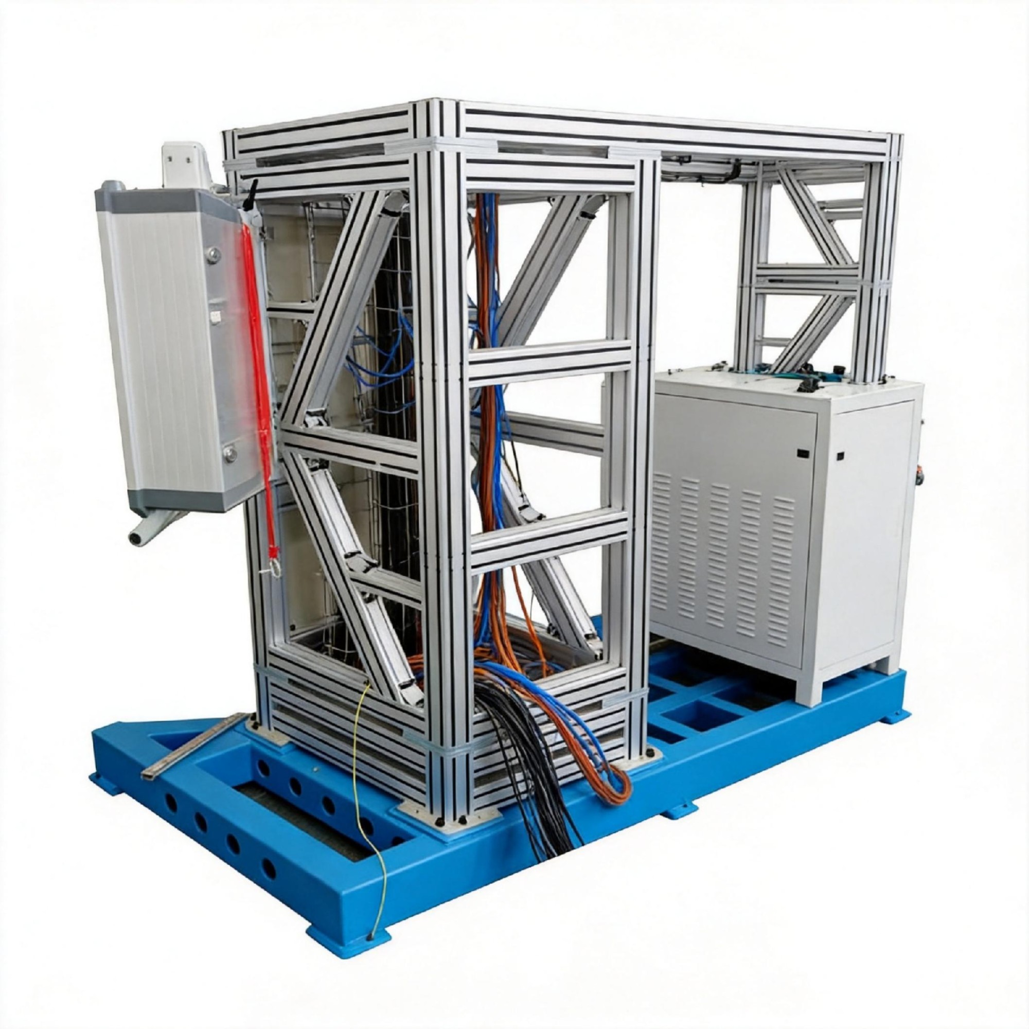
Quartz Fiber Optic Drawing Tower
- Product Item : AT61008
- Category: Optical Fiber & Cable Production Equipment
- Product description:
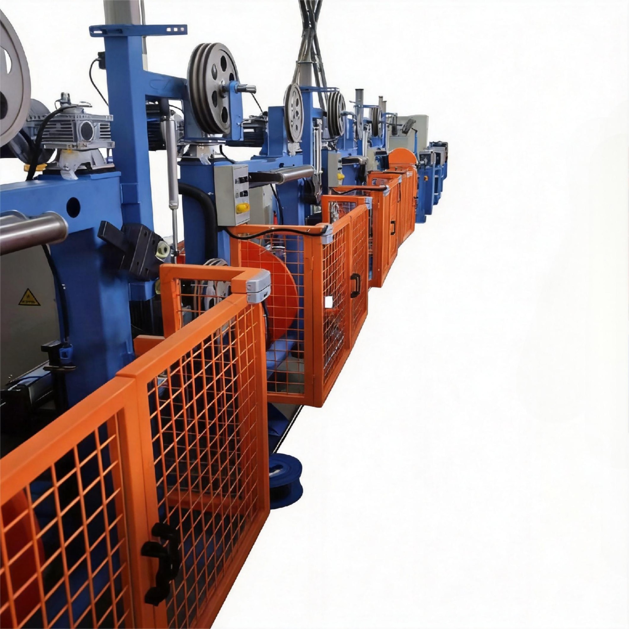
Wire drawing machine
Special Wire Drawing Production Line
Equipment Purpose:
To draw preforms with diameters ranging from Φ10 to 60mm into optical fibers, optical rods, or capillary tubes with diameters of Φ0.125 to 1.0mm as required by the process, and to coat their surfaces with UV-curable resin, polyimide coating, or metal coating to produce various types of specialty optical fibers with different functions.
|
Equipment Performance |
|
|
Equipment Configuration |
Single Tower Single (Double) Line |
|
Tower Height |
2.5~15m |
|
Drawing Material |
Quartz or Soft Glass |
|
Drawing Speed |
1-300m/min |
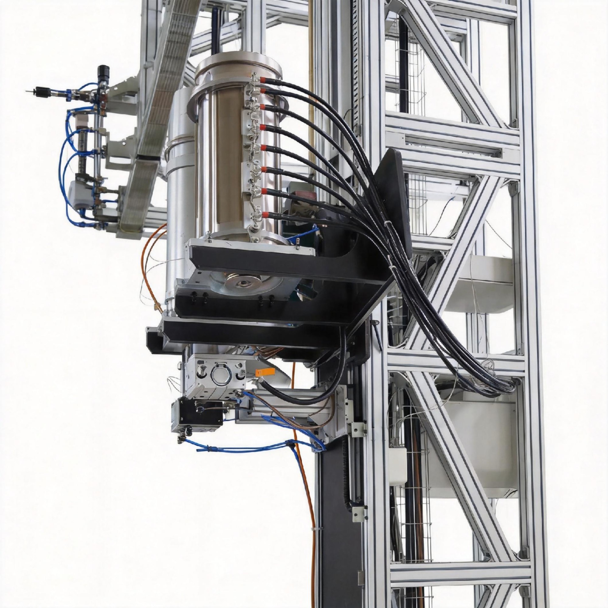
Preform Feeding Device:
Structural Description:
This machine adopts a rapid preform feeding device composed of an AC motor and a worm reducer. The preform is clamped on a three-jaw chuck, which has a water-cooled thermal insulation device underneath. The X-Y centering device for the preform relative to the electric furnace is manually adjustable. A rotation device for the preform can be clamped on the three-jaw chuck, driven by an AC servo motor, with a rotation speed of 0-2000r/min. The feeding device is equipped with its own control box for easy operation.
|
Technical Requirements |
|
|
Preform Diameter |
Ф10-Ф60mm |
|
Preform Diameter Accuracy |
±0.5mm |
|
Preform Length |
1200mm |
|
Feeding Speed |
0.5-20mm/min |
|
Rapid Feeding Speed |
300mm/min |
Resistance Graphite Heating Furnace:
Structural Description:
The graphite furnace consists of a furnace body, a high-frequency switching power supply, a temperature measurement and control system, a water and gas cabinet, and vacuum pumping. The furnace body is made of stainless steel welding parts, with cooling water applied to the outer wall for temperature reduction. The furnace interior is heated by graphite, with insulation layers provided. The furnace is connected to an argon protection gas circuit controlled by a mass flow meter.
|
Technical Specifications |
|
|
Heating Temperature |
1500-2300℃±1℃ |
|
Preform Diameter |
Φ15 -Φ80mm |
|
Heating Power |
15-45KW |
Bare Fiber Diameter Gauge
|
Bare Fiber Diameter Gauge |
|
|
Measurement Range |
0.008~5mm |
|
Accuracy |
0 .0005 |
|
Scanning Rate |
1200 times/sec |
|
Resolution |
0.0001 |
|
X-Y Micromanipulator Below Gauge |
|
Auxiliary Traction:
The auxiliary traction device located above the coating is used for drawing the initial stage of the wire to stabilize and uniform the fiber diameter, allowing it to smoothly pass through the coating mold. After the optical fiber undergoes coating and curing , it enters the main traction device or the auxiliary traction device located below the curing section, at which point the auxiliary traction stops working.
The auxiliary traction device located below the curing section is used for traction when drawing thick-diameter optical fibers. With this auxiliary traction device, the optical fiber is cut off or manually wound below it without entering the main traction device and winding device. The auxiliary traction wheels are made of antistatic insulating ester, which does not generate static electricity on the optical fiber and has elasticity to prevent damage to the optical fiber. Traction speed: 0~10m/min.
Coating Device
The machine is equipped with both pressure-type and open-type coating cups for users to choose from. The pressure-type coating system includes: pressure cup, heater, storage tank, and pressure feed system. The coating cup is mounted on a five-dimensional fine- tuning stand to adjust the concentricity of the coating.
It adopts a circulating water bath for temperature control of the coating system. A heat-tracing coating tube is selected.
Both pressure-type and open-type coating devices are provided, wherein the opening of the open-type coating cup can pass a preformed rod material with a diameter of 25mm.
UV Curing Oven
The UV curing oven consists of three parts: the curing oven, nitrogen supply, and exhaust. The curing oven is equipped with UV lamp tubes, and the power supply power can be adjusted to cure at different drawing speeds.
The middle hole size of the quartz tube in the UV curing oven is designed according to the rod material size to ensure that the preformed rod material can pass through.
Main Traction Drawing Tension Detector
The main traction is installed on the ground and adjusted to be coplanar with the optical fiber through an X-Y adjustment bracket. It adopts an AC servo motor to directly drive the traction wheel through a reducer, using a belt-wheel structure to traction the optical fiber. The belt is manually tensioned.
A tension sensor is installed on the main traction device, adopting a three-wheel tension detection structure . The tension detector is sourced from Beijing. The tension signal is only used for display to prompt process personnel to adjust the graphite furnace temperature and is not used as a basis for automatic control.
The main traction device has an antistatic function.
|
Technical Parameters |
|
|
Structural Speed |
300m/min |
|
Process Speed |
0.5~150m/min |
|
Speed Control Accuracy |
Set Value ±0.1% |
|
Traction Wheel Diameter |
500mm |
|
Traction Wheel Surface Treatment |
High-hardness Nickel-plated Steel |
|
Safety Protection |
Transparent Guard Cover |
|
Meter Counting Accuracy |
±10mm |
|
Static Electricity Elimination |
Equipped with Static Eliminator |
Dancer and Wire Take-up & Pay-off Device
Structure Description
The dancer adopts a multi-wheel pendulum lever structure, adjusting the position of the counterweight pendulum lever to regulate the take-up tension.
Manual loading and clamping are performed, with a cantilever shaft-type loading method. A frequency conversion motor drives the take-up reel to rotate via a worm reducer. A wire laying method with the reel moving is adopted, and an AC servo motor drives the lead screw for wire laying via a precision reducer. Proximity switches are used for reversing, and proximity switches and limit stops are configured at both ends of the wire laying for limit protection. There is an independent operation station, equipped with an antistatic device.
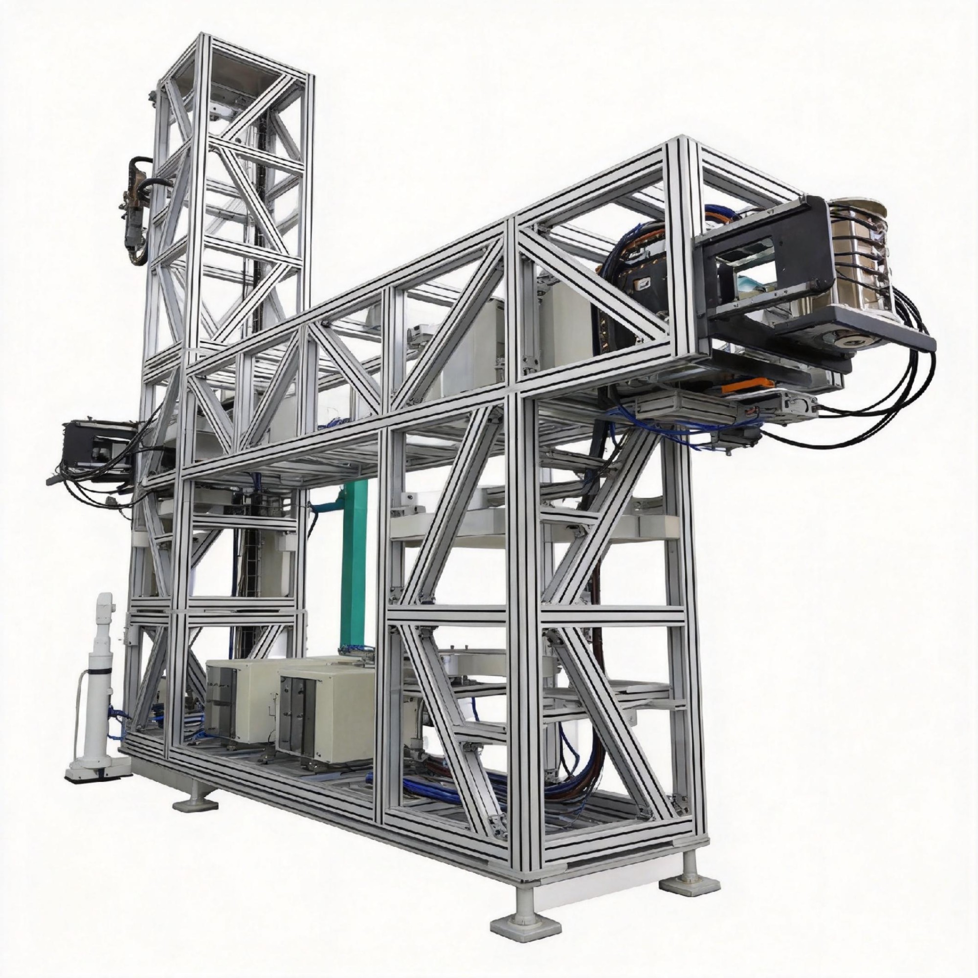
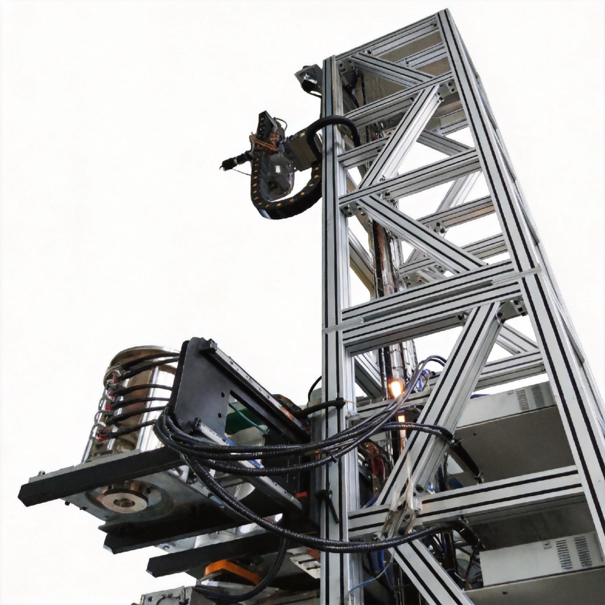
Tower
Installation Form:Pre embedded foundation bolts; the tower is fixed on the anchor bolts, and the verticality of the tower is adjusted by adjusting the bolts; the bolts between towers are tightly connected.
Tower Structure: There are two forms, aluminum profile spliced towers, and square tube welded towers (requiring artificial aging or tempering treatment). Both adopt a building-block method to splice sections of the tower together, freely combined to the height required by the customer.
Electrical Control System
The electrical control system of the special optical fiber drawing machine adopts IPC+PLC. The electrical control system is equipped with a main control cabinet (2000*1200*600). An operation station for stick feeding and graphite furnace control is set beside the top-layer stick feeder. A PLC slave station box is installed on the side of the stick feeder. Two auxiliary tractions are equipped with operation button stations for convenient local operation and control. An auxiliary traction operation button box is set beside the main traction, and an operation station is configured for the wire take-up device.
Function Program - Graphite Furnace Temperature Control
The heating zone height of the graphite furnace heating element is generally 40mm , with an inner diameter of 35~40mm and a wall thickness of 2.5~3.5mm, making the thermal inertia of the graphite furnace very small. If heated at full power, it will reach 2200°C in 10~15 seconds. Rapid temperature rise will seriously affect the life of the heating element and the metal parts of the graphite furnace.
After setting the heating temperature and heating time on the IPC human-machine interface, the PLC program calculates the heating curve and gradually increases the heating power according to this curve until the set value is reached. The display range of the temperature controller is 800~3000°C. When it is below 800°C, the temperature controller outputs constant power, which is processed by the PLC and heated at the set power. Generally, when the temperature reaches 900°C, it switches to temperature controller control, and PLC limiting is adopted to prevent temperature mutation before outputting to the high-frequency switching power supply.
The IPC interface is equipped with graphite furnace temperature rise and fall buttons to increase or decrease the set temperature by a set step.
During the operation of the graphite furnace, the protective gas flow rate, protective gas pressure, and circulating water flow rate are detected in real-time. An alarm is triggered when the pressure is too low, but the furnace does not stop. In case of gas or water interruption faults, an alarm is triggered, and the furnace stops immediately.
Curing Power and Curing Oven Exhaust Fan Control
Curing power generally has two setting methods: manual, where the operator sets the curing power value on the human-machine interface (setting range: 10~100%), and automatic, where the process engineer sets it in the corresponding table of curing power and drawing speed.
For the first method, the PLC directly processes the data and gives a curing power setpoint signal according to the set value. For the second method, the PLC calculates the corresponding curing power according to the current speed based on the curing power and drawing speed correspondence curve (using a piecewise fitting method) and outputs the curing power signal.
It is recommended to use the first method in the initial stage of drawing. Once experience has been accumulated, the second method is safer and more reliable.
During the curing process, the temperature of the curing oven is detected in real-time, and the rotational speed of the exhaust fan is adjusted according to the detected temperature to regulate the airflow. Too low a temperature results in incomplete curing, while too high a temperature can burn the optical fiber.
Function Program - Fiber Diameter Control
Diameter is an important parameter for assessing optical fiber performance. Usually, the stick feeding speed remains constant during the operation of the drawing machine, and the optical fiber will not change after leaving the melting point, so the traction speed determines the diameter of the optical fiber. Generally, the diameter measuring instrument is installed at a distance of 1~1.5m from the exit point. If the measured fiber diameter is too large and the traction speed is increased, it may result in the fiber diameter being too thin, thus forming an oscillation in the fiber diameter.
Fuzzy control is adopted instead of the PID adjustment method to incrementally adjust the traction speed, which has been successfully applied in high-speed communication optical fiber drawing machines and other special optical fiber drawing machines.
Electrical Control System - Human-Machine Interface
The human-machine interface is equipped with the main control screen, engineer parameter setting screen, running status screen, real-time curve screen, historical curve screen (graphite furnace temperature, drawing speed, curing power, bare wire diameter), fault alarm screen, etc.
Graphite furnace temperature, drawing speed, and optical fiber diameter are three important parameters during the operation of special optical fiber drawing machines, which can be displayed on every screen.